|
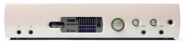
Atlas's front panel contains a limited number of physical controls and indicators. A greater degree of control is available using the Atlas Control Panel app software provided. The front panel also contains the instrument input and headphone output jacks.
From left to right:
| • | Instrument input jacks 1&2: mono unbalanced jacks, high impedance, with finely adjustable gain control. See Analogue inputs. |
| • | Assignable level control: Volume knob which can be assigned to any of Atlas's outputs (except for the headphone output), as required. This is primarily intended as a monitor volume control for stereo monitoring. Note that pressing the knob mutes any outputs assigned to the control; this state is indicated by the LED halo around the knob flashing. |
| • | Headphone jacks 1&2: each with its own volume control. |
| • | Standby button: puts the unit into a low-power standby state. Note that the USB interface is still active in standby mode, so the Atlas unit can still be recognised by the host, although its inputs and outputs are inactive. The LED in the standby button flashes to identify the unit in multi-unit setups when the 'Identify' button in the Control Panel app is clicked. Entering standby mode causes Atlas to retain its current software control settings in flash, for example for use in stand-alone mode. |
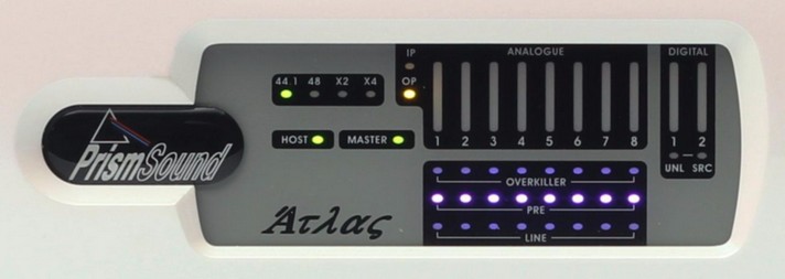
Meter panel
The meter panel contains metering for the analogue input and output channels and the S/PDIF input and output channels. It also contains the input selection indicators and Overkiller activity indicators for all the analogue inputs, unlock and SRC indicators for the S/PDIF input, and an SRC indicator for the S/PDIF output.
From left to right:
| • | Sample rate indicators: these indicators show the sample rate of the main Atlas signal path. Standard rates of 44.1kHz, 48kHz, 88.2kHz, 96kHz, 176.4kHz and 192kHz are supported. For more information, see the Unit settings section. |
| • | Host indicator: this indicator is normally lit green, to show that Atlas is connected to the host computer via the USB interface; however, when lit red, it indicates that the unit is using the MDIO (multi-channel digital IO) expansion module to connect to a non-USB host, as described in the MDIO expansion slot section. Note that future firmware/software may allow host connection via Ethernet, in which state the Host indicator will be lit orange. |
| • | Master indicator: this is lit when the device is set to local (internal) sample clock, and off when locked to an external sync source; it flashes when local sync has over-ridden an invalid external sync source selection. For more information see the Synchronization section. |
| • | Meter input/output indicator: shows whether the bar-graph meters are assigned to the analogue and S/PDIF inputs (IP indicator is lit), or to the analogue and S/PDIF outputs (OP indicator is lit). This is selected in the Atlas Control Panel app. See the Metering system section for more details. |
| • | Overkiller indicators: indicate that the Overkiller progressive limiter is operating in that channel. Note that the indication is dynamic, and shows when the Overkiller is actually limiting, and not simply that it is enabled. Note that the Overkiller indicators are only active when the meters are in input mode. In output mode, these indicators flag a Verifile checker error in the corresponding DAW output if that signal is Verifile-encoded. If the signal is not Verifile-encoded, or if there is no error, the indicator is not lit. |
| • | Input selection indicators: these indicators show the analogue input selections; the LINE indicator is lit green for line, or the PRE indicator is lit pink for mic or blue for instrument preamplifiers. The mic selection indicators change from pink to red to indicate that phantom power is switched on. See Analogue inputs. |
| • | DI unlock indicator ('UNL'): indicates that the S/PDIF input is unlocked, i.e. no S/PDIF carrier is recognised; only active when the meters are in input mode. In output mode, this indicator flags a Verifile checker error in either channel of the DAW DO output if it is Verifile-encoded. If the signal is not Verifile-encoded, or if there is no error, the indicator is not lit. |
|


