dScope Series III Architecture Guide
SIGNAL GENERATOR ARCHITECTURE
The settings for the dScope generator are accessed through the Signal Generator dialogue box (shown below).
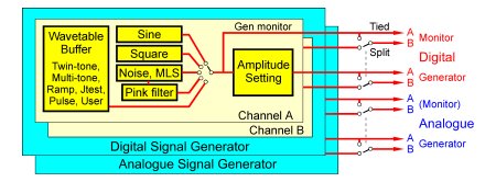
The dScope Signal Generator may be considered as four separate generators: one for each Analogue Output channel and one for each Digital Output channel. In 'Tied' mode, the A and B channel outputs are the same (although they may be turned on and off individually in both domains). In 'Split' mode, each channel may be driven with different amplitude and frequency, or even with entirely different generated functions. Analogue and Digital Outputs are generated simultaneously, and presently the software forces the outputs in the two domains to be driven with equivalent signals, i.e. 'domain split' mode is not possible. When either the analogue or Digital Outputs are set to sample above 96kHz, Split mode operation is not possible.
The Signal Generators use real-time signal processing to generate sine, square and noise-based signals, whereas wavetables are used to generate other functions. The user can generate any arbitrary waveforms by loading the wavetables from files (dScope III '.wfm' format, dScope II '.usr' format, or Windows '.wav' format) or by writing a VBScript to fill the table.
The various Signal Generator outputs are available to the Monitor Outputs, as well as at the main Digital and Analogue Outputs.


