|
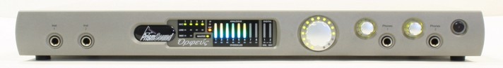
Orpheus' front panel contains a limited number of physical controls and indicators. A greater degree of control is available using the Orpheus Control Panel applet software provided. The front panel also contains the instrument input and headphone output jacks.
From left to right:
| • | Instrument input jacks 1&2: mono unbalanced jacks, high impedance, with finely adjustable gain control. See Analogue inputs. |
| • | Assignable level control: Volume knob which can be assigned to any of Orpheus' analogue or S/PDIF outputs, as required. This is primarily intended as a monitor volume control for stereo or surround monitoring. |
| • | Headphone jacks 1&2: each with its own volume control. |
| • | Standby button: puts the unit into a low-power standby state. Note that the FireWire interface is still active in standby mode, so the Orpheus unit can still be recognised by the host, although its inputs and outputs are inactive. The LED in the standby button flashes to identify the unit in multi-unit setups when the 'Identify' button in the Control Panel applet is clicked. Entering standby mode causes Orpheus to retain its current software control settings in flash, for example for use in stand-alone mode. |
Meter panel
The meter panel contains metering for the eight analogue input and output channels and the two S/PDIF input and output channels. It also contains input selection indicators for inputs 1-4, Overkiller activity indicators for all the analogue inputs, unlock and SRC indicators for the S/PDIF input, and an SRC indicator for the S/PDIF output.
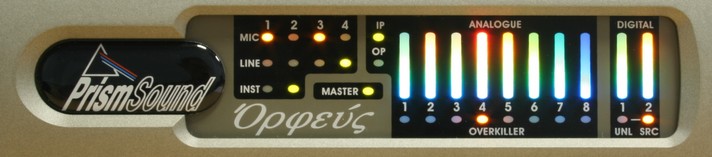
From left to right:
| • | Input selection indicators: inputs 1-4 auto-select whichever type of input device is plugged in; these indicators show the state of the selection; mic, instrument or line for inputs 1&2, mic or line for inputs 3&4. The mic selection indicators change from green to orange to indicate that phantom power is switched on. See Analogue inputs. |
| • | Master indicator: this is lit when the device is sample clock master (from the FireWire bus point of view). If a device is configured to be clock master, but is itself slaved to a wordclock or DI reference which is absent or at a different frequency from the selected sample rate, the master indicator flashes. For more information see the Synchronization section. |
| • | Meter input/output indicator: shows whether the ten bar-graph meters are assigned to the analogue and S/PDIF inputs, or to the analogue and S/PDIF outputs. This is selected in the Orpheus Control Panel applet. See the Metering system section for more details. |
| • | Overkiller indicators: indicate that the Overkiller progressive limiter is operating in that channel. Note that the indication is dynamic, and shows when the Overkiller is actually limiting, and not simply that it is enabled. Note that the Overkiller indicators are only active when the meters are in input mode. |
| • | DI unlock indicator: indicates that the S/PDIF input is unlocked, i.e. no S/PDIF carrier is recognised. Only active when the meters are in input mode. |
|


