dScope Series III Architecture Guide
ANALOGUE INPUT ARCHITECTURE
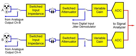
The figure above illustrates the functionality of the dScope's Analogue Input conditioning circuits. The below is the dScope application dialogue for this section.
The Analogue Inputs can accept balanced or unbalanced inputs up to +46dBu (154.5V RMS). The dScope software sets the input range by adjusting the switched attenuator and variable gain stage in each channel. Normally this is done automatically, but the operator can fix the input range manually if desired.
The input impedance can be selected from 100kR, 600R, or a low impedance which is either 150R or 200R according to a PCB jumper setting. The dScope software is aware of the jumper setting and only offers the jumpered setting in the user-interface. The dScope software may over-ride the input impedance to 100kR if the input amplitude is high enough to damage the termination resistor. The termination resistors are also protected by a fuse in each channel.
The Analogue Inputs are normally DC-blocked by a capacitor, but this may be bypassed by a PCB jumper setting if DC-coupled analysis is needed.
The Analogue Input circuit is normally sourced from the XLR and coaxial input connectors (in parallel) but may be switched to be driven from the analogue Generator outputs if required. This allows direct analysis of the Generator outputs without re-plugging. Alternatively, since the Generator feed is from the opposite channel, the two Analyzer channels can be switched to measure the input and output of a device under test simultaneously, one channel at a time, so that input-to-output transfer measurements can be made.
The demodulated jitter signal from the selected Digital Input can also be switched to over-ride the Analogue Inputs if desired. This allows the incoming jitter to be displayed as a Scope Trace, or its spectrum as an FFT. In this case, the second Analyzer channel is disabled.
NOTE!
The outer conductors of the Analogue Input BNC connectors are connected to the inverting leg of the balanced input circuit (i.e. to pin 3 of the associated XLR) and not to chassis or signal ground.The Analogue Input sample rate can be switched between 48kHz and 192kHz. In the current software versions, the Analogue Input ADC and the Analogue Output DAC share the same sample clock, so switching the rate of the ADC also controls the rate of the DAC.


